
Leave Your Message

How to Choose the Right Current Transformer Cabinet?

Choosing the right Current Transformer Cabinet requires more than comparing enclosure sizes and price tags. The cabinet must support accurate measurement, safe isolation, and dependable operation under real electrical conditions. A well-selected design protects meters, relays, and maintenance staff from avoidable risks.

Begin by examining the system’s voltage, primary current, short-circuit level, and installation environment. The transformer ratio should match the expected load, not only today’s reading. Accuracy class and burden rating also matter, especially when revenue metering or protection relays are involved. A cabinet installed outdoors may need weather resistance, ventilation, anti-condensation measures, and corrosion protection. Small details matter here.

Look closely at terminal access, cable bending space, grounding points, and inspection visibility. Experienced engineers often review wiring diagrams beside the physical layout. This catches problems that product brochures can hide. The neatest cabinet is not always the most practical one. A crowded terminal row can turn routine testing into a frustrating task. It may also increase maintenance errors.

Reliable selection should follow applicable electrical standards and the project’s local inspection requirements. Confirm test reports, factory quality controls, and the manufacturer’s technical support before ordering. Do not rely on a familiar model without checking its actual operating conditions. That shortcut feels efficient. Sometimes it is not.

This guide explains the key decisions behind a suitable Current Transformer Cabinet. It connects technical specifications with field conditions, maintenance needs, and long-term reliability. The goal is not merely to choose a cabinet that fits. It is to choose one that performs clearly, safely, and consistently when the system matters most.
How to Choose the Right Current Transformer Cabinet?

Define the Purpose and Operating Conditions of the Current Transformer Cabinet

Selecting a current transformer cabinet starts with its purpose, not its appearance. Is it measuring revenue, protecting a feeder, or supporting power-quality monitoring? Each purpose changes the required accuracy class, burden, ratio, insulation level, and wiring arrangement. IEC 61869-2 defines performance requirements for measuring and protective current transformers, including accuracy and burden considerations.

Operating conditions must be documented before specifying the cabinet. Record normal load current, short-circuit current, system voltage, frequency, ambient temperature, humidity, altitude, and available installation space. The IEA Electricity 2024 report states that global electricity demand grew by 2.2% in 2023 and may grow by about 3.3% annually from 2024 to 2026. That growth makes future load assessment important. Oversizing is not always safer.

The U.S. Energy Information Administration’s Electric Power Annual reports transmission and distribution losses of roughly 5% in recent years. Poor measurement cannot explain every loss, but it can hide wiring errors, unbalanced loads, or overloaded circuits. Specify shorting terminals, clear phase identification, grounding points, and safe access for testing. A cabinet exposed to dust or condensation may need a higher enclosure rating and anti-condensation heating. Small details matter.

Field experience also shows a common weakness: engineers sometimes use maximum load data only. That is incomplete. Minimum load can affect metering accuracy, while fault current determines protection performance. I would verify both conditions, then review the design with the operator. A clean drawing can still miss real maintenance habits.


Select the Correct Transformer Type, Ratio, and Accuracy Class

How to Choose the Right Current Transformer Cabinet?

Selecting a current transformer cabinet starts with the transformer type. Window transformers suit fixed busbars and offer simple installation. Bar-type transformers provide stronger mechanical support in higher-current assemblies. Wound transformers can serve unusual ratios, but they need closer technical review. For maintenance projects, split-core units may reduce downtime. That convenience has limits.

Choose the ratio from the actual maximum load, not only the breaker rating. A 600/5 A transformer may perform poorly when the normal current stays near 40 A. Oversizing is a common shortcut. It can reduce measurement quality at low loads. Leave reasonable capacity for future expansion, but confirm the expected operating range with recorded load data. I once trusted nameplate ratings too quickly, and the result was a less useful measurement than planned.

Accuracy class must match the application. Metering systems often require classes such as 0.2S, 0.5, or 1.0. Protection circuits may require 5P or 10P performance. These markings are not interchangeable. Check the applicable standard, rated burden, frequency, and knee-point requirements. The cabinet should also include secure secondary terminals, clear phase identification, and suitable insulation distances. Never leave a CT secondary open while the primary is energized. Small details matter. Verify conductor placement, grounding, and wiring torque during commissioning. A final burden test is worthwhile, although it is sometimes skipped under schedule pressure.

How to Choose the Right Current Transformer Cabinet? - Select the Correct Transformer Type, Ratio, and Accuracy Class
Current Transformer Type Typical Primary Current Range Typical Secondary Recommended Ratio Examples Metering Accuracy Class Protection Accuracy Class Typical Burden Range Suitable Cabinet Application Key Selection Considerations
Wound Primary CT 5 A to 600 A 1 A or 5 A 100/5 A, 200/5 A, 400/5 A Class 0.2S, 0.5S, or 0.5 5P10 or 5P20 when specified for protection 5 VA to 30 VA Low- and medium-voltage metering cabinets with a defined primary conductor path Provides a dedicated primary winding and can offer good accuracy at low primary currents. Confirm insulation level, rated frequency, and terminal arrangement.
Bar-Type CT 100 A to 5,000 A 1 A or 5 A 400/5 A, 800/5 A, 1,600/5 A, 3,000/5 A Class 0.5, 0.5S, or 1.0 5P10, 5P20, or PX, depending on the protection scheme 5 VA to 30 VA Switchboards, busbar compartments, feeder panels, and high-current distribution cabinets The busbar or cable passes through a fixed primary window or opening. Verify the opening size, busbar dimensions, phase spacing, and short-time withstand requirements.
Window-Type CT 50 A to 4,000 A 1 A or 5 A 200/5 A, 600/5 A, 1,000/5 A, 2,000/5 A Class 0.5, 0.5S, or 1.0 5P10 or 5P20 5 VA to 30 VA Retrofitted cabinets and installations where the existing conductor must pass through the CT aperture Check the actual cable or busbar outside dimensions and required clearance. Multiple primary passes can change the effective ratio and must be allowed by the design.
Split-Core CT 50 A to 2,000 A 1 A or 5 A; some models provide a low-level output 250/5 A, 500/5 A, 1,000/5 A Class 0.5, 1.0, or 3.0, depending on construction Generally not preferred for high-speed or high-accuracy protection Typically 1 VA to 10 VA Existing energized systems, retrofit monitoring, and compact measurement cabinets Useful when conductor disconnection is impractical. Confirm hinge and core closure, installation orientation, conductor position, and accuracy at the actual current level.
Residual or Core-Balance CT Designed for residual current measurement rather than normal load current 1 A or 5 A 100/1 A, 200/1 A, or manufacturer-defined residual ratio Application-specific; commonly Class 5P or a dedicated sensitive earth-fault specification 5P10, 5P20, or a specified sensitive earth-fault characteristic 5 VA to 15 VA Earth-fault protection cabinets and residual-current monitoring systems All phase conductors, and the neutral where applicable, normally pass through the same core. The protective relay sensitivity and maximum cable aperture must be checked together.
Multi-Ratio CT 100 A to 3,000 A 1 A or 5 A 300-600/5 A, 600-1,200/5 A, 1,000-2,000/5 A Class 0.5, 0.5S, or 1.0 on the selected tap 5P10, 5P20, or PX on the selected tap 10 VA to 30 VA Projects with future load expansion or several approved operating ratios Only the designated tap should be used in service. Unused taps must be terminated as required by the CT documentation, and the selected tap must match the relay or meter burden.
Protection-Class CT 100 A to 5,000 A 1 A or 5 A 400/1 A, 800/1 A, 2,000/5 A Not normally selected for revenue metering 5P10, 5P20, 10P10, 10P20, or PX 15 VA to 30 VA or as calculated Overcurrent, earth-fault, differential, and other protective relay circuits Choose the class from the protection study. For differential protection, knee-point voltage, excitation current, winding resistance, and lead resistance may be more important than a simple 5P rating.
Metering-Class CT 5 A to 3,000 A 1 A or 5 A 100/5 A, 400/5 A, 1,000/5 A Not intended to replace a dedicated protection CT 5 VA to 15 VA Energy metering cabinets, power-quality panels, and commercial measurement systems Class 0.2S and 0.5S performance is specified over defined current ranges. Match the CT ratio to the expected load so the normal operating current is not far below the accuracy range.
Low-Voltage CT 50 A to 6,000 A 1 A or 5 A 250/5 A, 1,000/5 A, 4,000/5 A Class 0.5, 0.5S, or 1.0 5P10 or 5P20 5 VA to 30 VA Low-voltage switchboards, motor-control centers, and feeder measurement sections Confirm the system voltage, insulation level, enclosure clearances, short-circuit withstand, and whether the CT is suitable for the cabinet’s conductor arrangement.
Medium-Voltage CT 50 A to 4,000 A 1 A or 5 A 100/1 A, 400/5 A, 1,200/5 A Class 0.2S, 0.5S, or 0.5 5P20, PX, or another specified protection class 10 VA to 30 VA Medium-voltage switchgear, incoming feeders, outgoing feeders, and transformer protection cabinets Verify highest system voltage, power-frequency withstand, lightning impulse withstand, creepage distance, insulation coordination, and CT placement relative to the circuit breaker.

Evaluate Electrical Ratings, Safety Features, and Protection Requirements

How to Choose the Right Current Transformer Cabinet?

Choosing the right current transformer cabinet begins with electrical ratings, not appearance. Confirm the primary voltage, secondary voltage, frequency, burden, accuracy class, and continuous current. The short-circuit withstand rating must match the installation’s fault level. A cabinet that fits physically may still perform poorly during faults. That can distort metering and delay protective action. Use updated load calculations and verified site records. Do not rely on an old drawing.

Safety features deserve equal attention. Check the enclosure rating for dust, moisture, impact, and indoor or outdoor exposure. The cabinet should include secure grounding, insulated barriers, clear labels, and accessible test points. Never leave an energized CT secondary open. This can create dangerous voltage and damage equipment. Protection requirements should match the relay system, including overcurrent and earth-fault functions. Confirm that CT accuracy remains suitable during expected fault currents. Small omissions matter.

Tips: Compare the cabinet’s thermal and short-time ratings with the actual switchgear. Review cable entry space before ordering. In practice, specifications are sometimes copied from previous projects. That is convenient, but unreliable. Ask an experienced electrical engineer to check coordination, installation access, and maintenance procedures. A final inspection should confirm tight connections, correct polarity, grounding, and intact barriers. Field conditions often reveal problems that drawings miss.

Compare Cabinet Design, Materials, Installation, and Maintenance Needs

How to Choose the Right Current Transformer Cabinet?

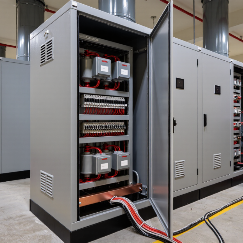
Cabinet design should match the transformer arrangement, conductor size, and access requirements. A spacious interior allows safer wiring and easier testing. Tight cabinets may reduce cost, but they often complicate repairs. Check clearances around terminals, busbars, and cable bends. The enclosure should also provide suitable protection against dust, moisture, and accidental contact.

Material selection affects service life. Powder-coated steel offers strength for indoor installations. Stainless steel performs better in corrosive or humid locations. Aluminum can reduce weight, but connections require careful attention to galvanic corrosion. Sealed joints, drainage paths, and secure grounding points are essential. Small details matter.

Installation quality directly affects measurement accuracy and safety. Verify polarity, ratio, phase identification, and secondary wiring before energizing. Never open-circuit an energized current transformer secondary. Use calibrated torque tools on terminals and record the results. Leave working space around the cabinet, especially near test links and protective devices. I have seen a well-designed cabinet fail because installers ignored cable stress. That mistake is easy to repeat.

Maintenance needs should influence the purchase decision. Choose removable covers, labeled circuits, and accessible inspection points. Inspect insulation, terminal tightness, corrosion, and unusual heat during scheduled service. Thermal scanning can reveal loose connections before damage occurs. Keep clear records of readings and repairs. No cabinet is perfect; reviewing field problems can improve the next specification.

Verify Standards, Testing, Supplier Quality, and Total Ownership Cost

How to Choose the Right Current Transformer Cabinet?

A current transformer cabinet should be chosen against verified standards, not attractive drawings. Ask for the exact standard edition, rated insulation level, temperature-rise limits, and enclosure protection rating. Request certificates matching the proposed model. Compare test reports, not only declarations. Routine tests should cover wiring, insulation resistance, polarity, ratio accuracy, and mechanical operation. Type tests matter too, especially for short-circuit withstand and temperature performance. One missing detail can delay approval.

Tips: Use a review sheet. Record each requirement, document, and approval status. Ask questions early. Vague answers often become expensive problems later.

Supplier quality deserves direct evidence. Visit the factory when possible, or arrange an independent inspection before shipment. Check calibration records, material traceability, torque control, and final inspection photos. Ask how nonconforming units are isolated. A reliable supplier should explain corrective actions clearly. Still, paperwork is not proof by itself. During site reviews, I have seen neat documents fail to reveal loose terminals or unclear labels.

Total ownership cost extends beyond the purchase price. Include installation hours, cable access, metering compatibility, spare parts, energy losses, maintenance visits, and expected service life. Compare warranty terms carefully. A cheaper cabinet may require costly rewiring later. Also assess delivery reliability and technical support response times. Leave room for uncertainty. Site conditions often differ from tender drawings. Verify dimensions, ventilation, fault levels, and access space before approval.